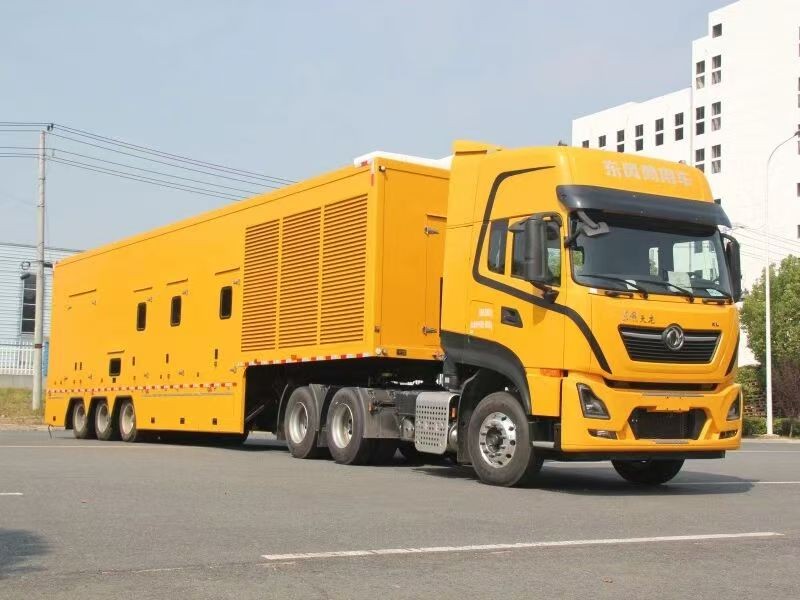
800–3000 kW medium-voltage mobile power units
800 kW is a genuine dividing line in mobile supply — not because large sets are hard to build, but because at 400 V the cable becomes too heavy to reel, the reel too large to fit, and the volt drop too high for the load at the far end. At medium voltage the same power is tens of amps and a single cable the thickness of a finger carries it 100 m. The price is a transformer, switchgear, protection settings and a set of type tests.
Short answer: above 800 kW, go to 6.6 kV or 11 kV. Three routes: ① LV set plus step-up transformer (most common, cheapest set, costs floor space); ② MV alternator generating directly (no transformer, 15–25% dearer); ③ several LV sets paralleled into one step-up unit. Protection settings, neutral earthing and cable terminations must all be redone to MV practice — an LV unit cannot simply be scaled up.
Why 800 kW: the current calculation
| Rating | 400 V full-load current | 400 V cable / mass per 100 m | 10.5 kV current | 10.5 kV cable / mass per 100 m |
|---|---|---|---|---|
| 400 kW | ~722 A | 2×185 mm² / ~660 kg | ~25 A | 25 mm² / ~30 kg |
| 800 kW | ~1,155 A | 3×240 mm² / ~1,300 kg | ~50 A | 35 mm² / ~42 kg |
| 1,200 kW | ~1,732 A | 4×240 mm² doubled / ~3,400 kg | ~75 A | 35 mm² / ~42 kg |
| 2,000 kW | ~2,887 A | no practical arrangement | ~125 A | 50 mm² / ~60 kg |
At 1,200 kW the LV route needs eight 240 mm² cores in parallel: 3.4 tonnes of copper and a reel over 2 m in diameter. That is not a question of cost — the cable physically will not fit on a vehicle and will not be dragged across a site. At 10.5 kV the same 1,200 kW travels on one 35 mm² core weighing 42 kg.
Three technical routes
| Route | Advantage | Penalty | Best for |
|---|---|---|---|
| LV set + step-up transformer | Standard set, cheap, spares everywhere, any mechanic can service it | Transformer takes 2–4 m² and 1.5–3 t; one extra 1.5–2% loss | 800–2,000 kW, most projects |
| MV alternator, direct generation | No transformer, one less loss (~1.5%), body 2 m shorter | Set costs 15–25% more, high insulation class, fewer models available | Above 1,500 kW, or length-limited |
| Multiple LV sets into one step-up unit | Smaller individual sets, easier transport, N+1 availability | Paralleling and protection coordination, longer commissioning | 2,000–3,000 kW, redundancy required |
Switchgear and protection: do not copy LV settings
Islanded MV generation is not grid supply. Fault current comes from the set itself and is limited, so the settings logic is different:
- Breaker: vacuum (VCB), rated current about 1.5× set rating, breaking capacity checked against the set's short-circuit contribution.
- Protection: overcurrent (definite and inverse time), instantaneous, negative sequence, earth fault, over/under voltage, over/under frequency, reverse power. Reverse power must be disabled or re-directed when islanded.
- Settings: a set typically delivers only 3–5× its rated current into a fault, limited by excitation and armature reaction. Settings copied from a grid feeder will simply fail to trip.
- Synchronising: voltage within 5%, frequency within 0.2 Hz, phase angle within 10° before closing. Islanded build-up needs no sync, but paralleling sets does.
- Metering and safety: CTs, VTs, voltage presence indicators, earthing switch and mechanical interlocks. A utility will not energise without them.
If the unit will run in parallel with the utility, obtain the connection agreement first — protection settings, earthing method and metering point are all approved by the utility, typically 4–8 weeks. That is the hidden critical path in most MV projects.
Neutral earthing: three options
| Method | Fault current | Advantage | Cost and use |
|---|---|---|---|
| Unearthed | Capacitive only, usually <10 A | Supply continues; an earth fault can run for 2 hours | Needs insulation monitoring; arcing over-voltage risk with long cable |
| Arc-suppression coil | <10 A residual after tuning | Suppresses arcing over-voltage, suits cable networks | Tuning follows network changes — awkward on a mobile unit |
| Low resistance | Typically 100–400 A | Definite settings, reliable tripping, limits over-voltage | Trips on the first earth fault; usual choice for mobile MV |
A mobile unit's cable length changes with every deployment, so capacitive current cannot be known in advance. Low-resistance earthing is the robust answer: fixed settings, reliable protection, independent of cable length. It trips on a single earth fault — which is the right trade for emergency supply.
MV cable reel: three details people miss
- Bending radius: not less than 15× overall diameter. A 10.5 kV 35 mm² cable is about 30 mm across, so the drum must be at least 450 mm and the finished reel 1.2–1.5 m in diameter.
- Terminations: MV terminations are cold-shrink or heat-shrink and cannot be made on site. Reel length is therefore fixed at works, with pre-made terminations at the end.
- Screen bonding: bonding both ends creates circulating current; bonding one end raises touch-voltage questions. Mobile units usually bond one end solidly and the other through a sheath voltage limiter, with the arrangement documented on the unit.
Practical note: lock the reel during transport and keep it dry. A damp termination will flash over in eight out of ten withstand tests, and re-terminating on site costs three to four days.
Four tests before delivery
| Test | Acceptance | Typical failure cause |
|---|---|---|
| Insulation resistance | 2,500 V tester, ≥1,000 MΩ | Moisture, contaminated termination |
| Power-frequency withstand | 28 kV / 1 min for 10.5 kV equipment (or 0.8× works value) | Termination defect, insufficient clearance |
| Partial discharge | ≤10 pC at 1.2× phase voltage | Busbar burrs, contaminated support insulators |
| Protection setting verification | Inject and confirm every element against the setting sheet | Wrong CT ratio, superseded setting sheet |
All four belong in the works test report; on site you only re-verify. Finding an MV defect after delivery costs far more than the equipment.
Price and lead time
| Capacity and route | Indicative FOB China | Lead time | Typical duty |
|---|---|---|---|
| 800–1,100 kW, LV set + step-up | USD 125,000–195,000 | 90–110 days | City distribution standby, substation support |
| 1,100–1,500 kW, MV alternator | USD 208,000–305,000 | 100–120 days | Major events, rail, airports |
| 1,500–2,000 kW, multi-set + step-up | USD 278,000–390,000 | 110–130 days | Regional emergency depots, industrial parks |
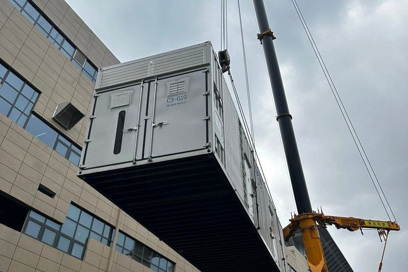
| 2,000–3,000 kW, semi-trailer or multi-box | USD 390,000–585,000 | 120–150 days | National response fleets, black start |
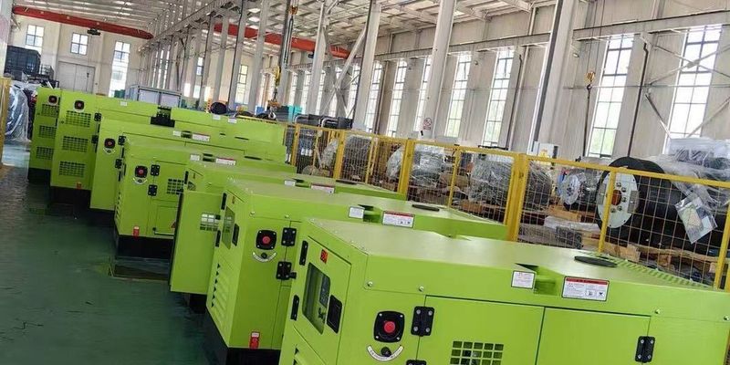
Cost mix is very different from LV: the set is only 40–50%, transformer/switchgear/protection 20–30%, body and trailer 15–20%, cable and reel 8–12%. Two quotes for the same 1,000 kW can differ by USD 30,000 purely on switchgear configuration — one incoming or two, single or duplicate protection.
Indicative FOB China references excluding freight, duties, connection studies and craning. Export configurations must state the destination voltage (11 kV / 13.8 kV / 33 kV) and the applicable standard (IEC or ANSI).
Questions buyers actually ask
Is medium voltage mandatory above 800 kW?
Not mandatory, but marginal. At 800 kW and 400 V the current is 1,155 A, needing 3×240 mm² and 1.3 t of copper per 100 m. With a 30 m reel and a fixed site LV still works; at 100 m MV is the better answer.
LV set with a transformer, or an MV alternator?
Below 1,500 kW take the step-up route: cheaper set, common spares, easier servicing. Above 1,500 kW, or when body length is constrained, the MV alternator earns its 15–25% premium by removing the transformer and one loss stage.
How should the neutral be earthed?
Low resistance for mobile MV: fixed settings, reliable protection, independent of cable length. Fault current typically 100–400 A, tripping on the first earth fault.
Can an MV unit run in parallel with the grid?
Yes, but obtain the utility's connection agreement first. Protection settings, earthing and metering point are approved by them, typically 4–8 weeks.
Why can the MV reel not be extended on site?
MV terminations are cold- or heat-shrink and need controlled conditions. Reel length is fixed at works with pre-made terminations; on site you can only connect pre-terminated joints.
Why is lead time over 100 days?
Set 35–45 days, transformer 30–40, switchgear 30–45 — in parallel still more than 60 days, plus integration, withstand and PD testing, and transport. Add 4–8 weeks if a utility connection study is required.
Fix the connection method before discussing price
Send the capacity, the required voltage (6.6 / 11 / 13.8 kV), whether it parallels the grid, cable length and transport constraints. You get a route recommendation, switchgear configuration and a price range.
Related: Mobile power units 20–3000 kW · 20–200 kW pickup & light truck · 200–500 kW truck-mounted · Containerised generators · Export process · Hospital standby · Data centre · Events · Emergency response